Sieg X2 CNC Conversion
I enjoy desktop 3D printing, and believe that it has opened up the possibility of small scale manufacturing to many people that would otherwise be unable to reach that capability. Importing an STL, auto generating support, and hitting print is incredibly easy compared to the alternatives.
Because I apparently enjoy pain, I decided to start looking at alternatives.
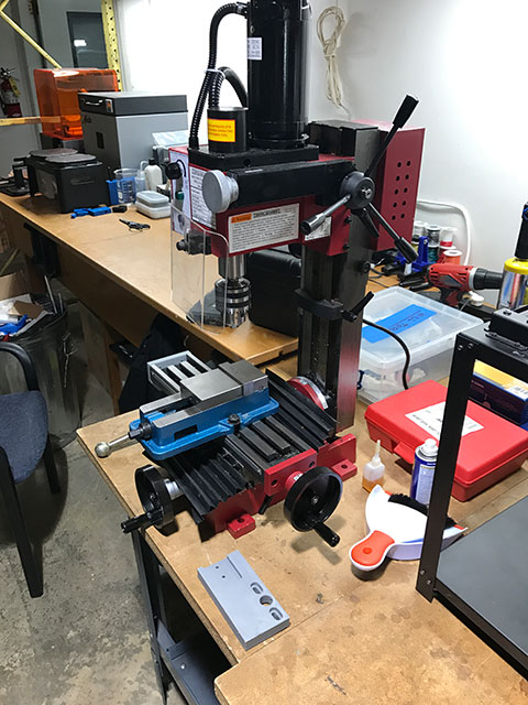
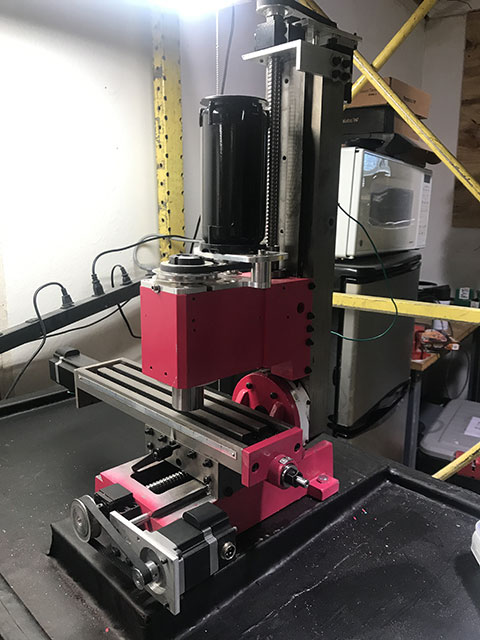
Above is a Sieg X2 Mini Mill, also known as the “Harbor Freight” mini mill. It’s a bit small and underpowered, but I was able to pick one up new for less than 400$ with a coupon. My initial plan was to use this mill to create some prototypes out of aluminum, since my 3D printed parts just couldn’t hold the tolerances I needed for my application.
I quickly found that this machine was great for milling straight lines, but I wanted more. So I told myself:
How hard could it be to build a CNC mill?
The answer, it turns out, is not that hard! Properly using a mill is what’s hard!
Here’s a couple videos of me badly using the mill:
Read on to see how we got to this point!
Getting Started
Just like my Basic 3D printer, I started with a 3D model. I found a basic model of the Sieg X2, and slowly added the detail necessary to create a fully fleshed out design .
Some components on the original mill (like the handwheels on the X and Y axis, and the Z-axis feed) were unnecessary, so I pulled them off.
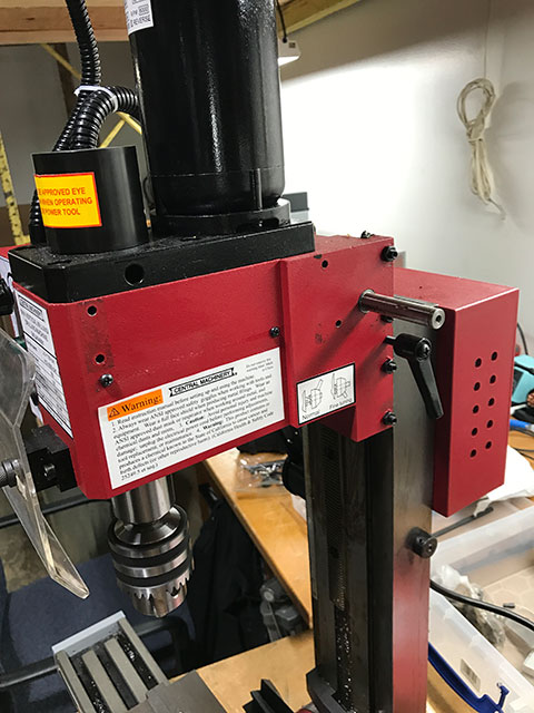
This opened up some space for my linear components and motors on the mill, but I wanted more. Traditional X2 CNC conversions put the Z axis ballscrew to the side of the back column, which is not ideal. It make much more sense to keep the ballscrew centered between the dovetail ways at the center of the column. Unfortunately there’s not really room for that.
Fortunately, I had access to a second mill!
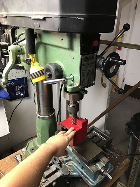
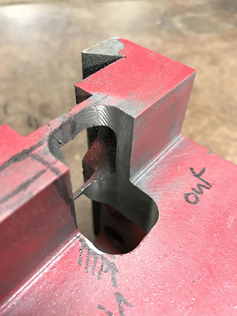
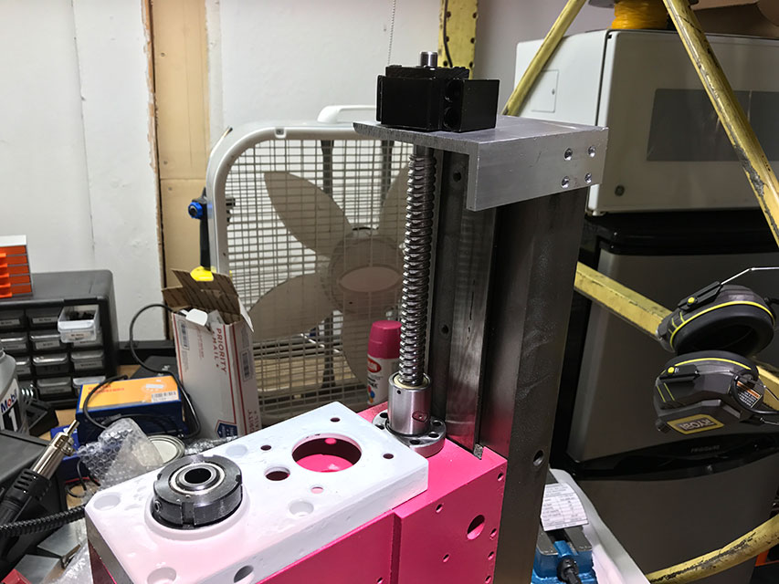
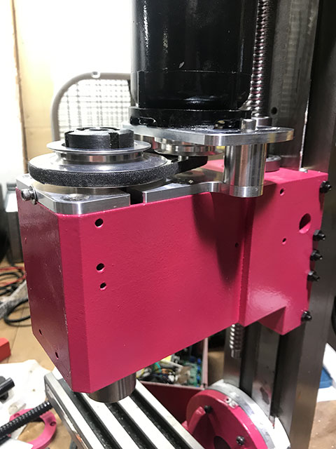
I was able to cut out a clearance hole for the Z axis ballscrew through the head of the mill, and mount the ballscrew nut directly on the underside of the head.
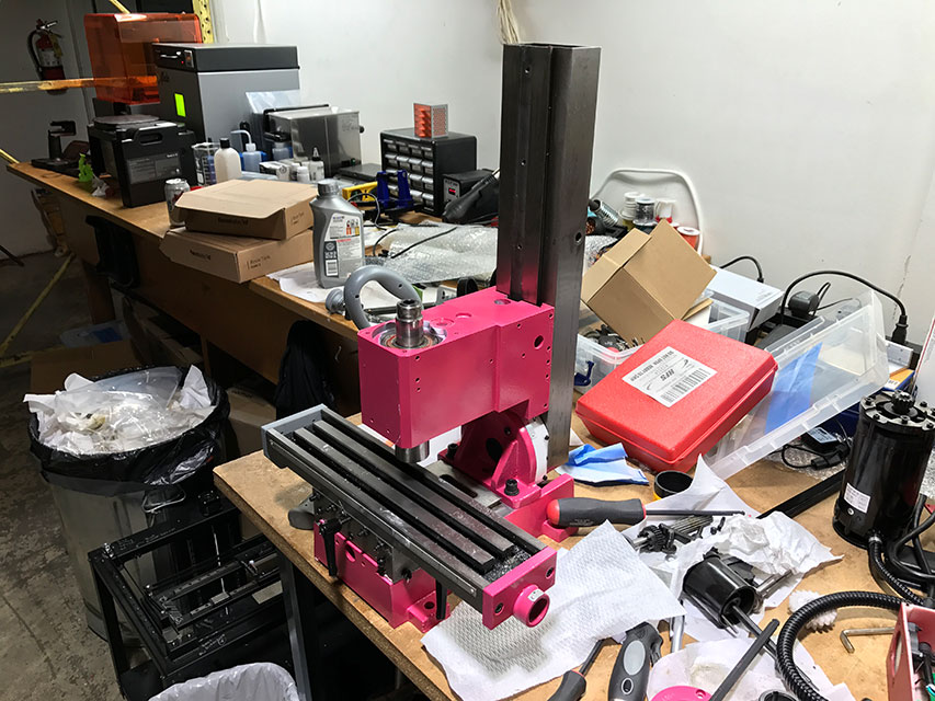
Since I had the mill in pieces anyways, I decided to do a deep clean and upgrade the paint job.
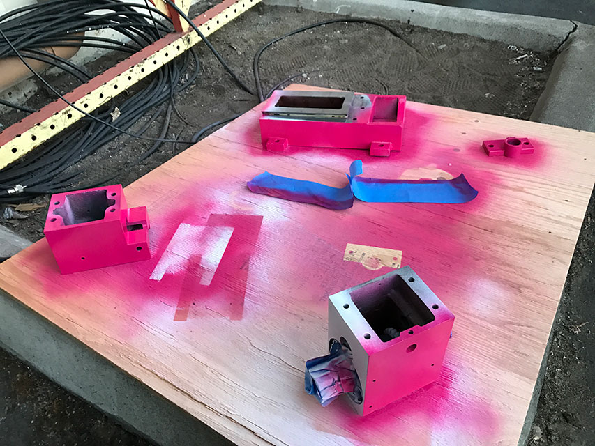
Putting the raw cast iron back together looks pretty good!
The Z Axis ballscrew bearing mount was fastened to the top of the Z axis using a chunk of aluminum angle
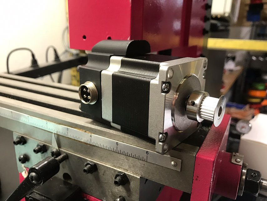
I wanted to make sure I had enough torque on the Z axis, so I connected my stepper motor using a 3:1 belt

I used a similar setup on the Y axis, and opted for a stronger, direct drive stepper motor on the X axis. I also 3D printed and soldered up some aircraft connector covers to prevent chips and dust from getting into the motors and help with wiring.
To drive the spindle, I stuck with the default R8 spindle and bearings, but upgraded to an off the shelf belt driven system. This made the mill run quieter since I could remove the plastic gears rattling around inside, and allows me to run my spindle at 5000 RPM instead of 2500 thanks to the pulley system.
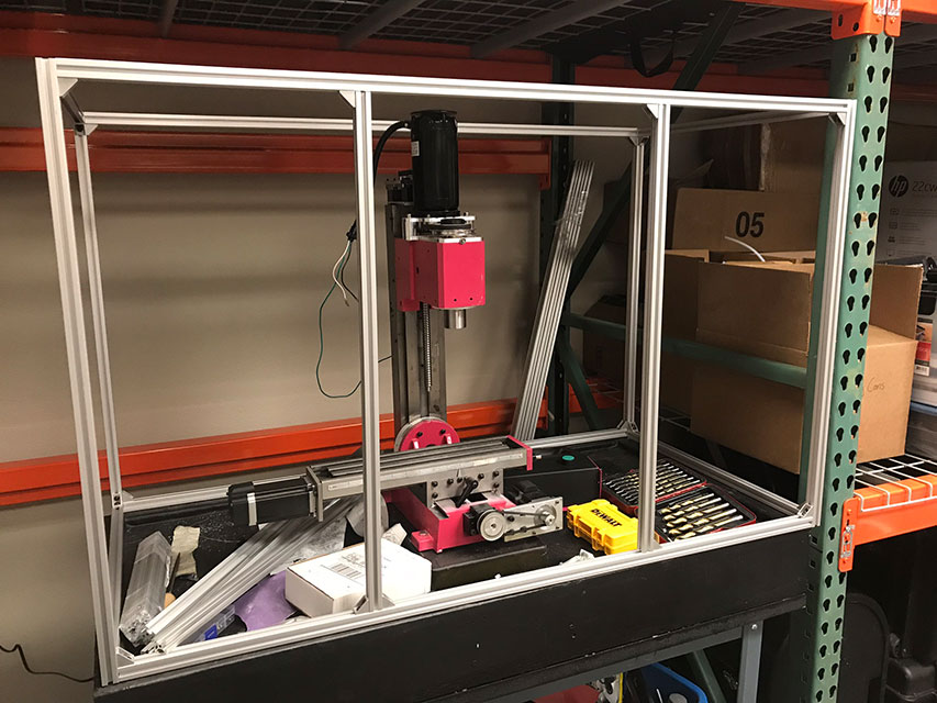
I wanted to avoid making a huge mess when machining – I had seen firsthand how far the chips could get flung by the spindle, so I decided to make a dedicated stand for the mill. This also had the benefit of increasing rigidity, since the mill is firmly bolted down the the table.
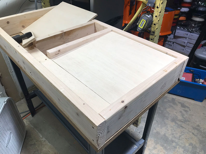
I started with a 2’ x 4’ table that I saved from the dumpster, and built up a little frame on it.
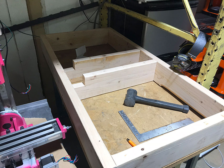
Additional blocking was added, as well as some plywood angled in such a way that there is one single low point.
At this particular point I had been thinking about add flood coolant to my mill. Adding all these slanted surfaces to the table was a lot of extra complexity, but was necessary to avoid having coolant pool and stagnate around the mill. I haven’t gone down this path yet, but it’s nice that this option is open to me.
I add some fiberglass and paint to waterproof this whole setup.
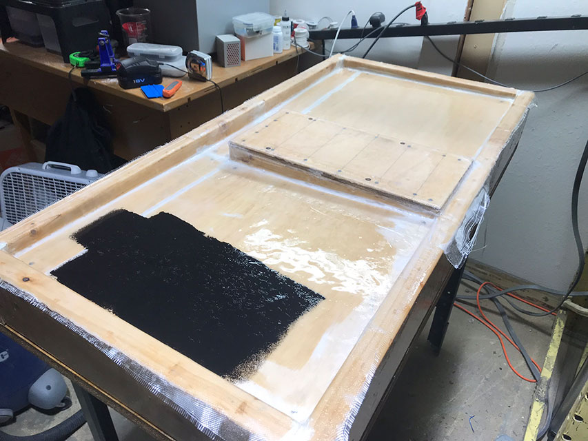
And we were ready for mounting!
Frame it in
I sometimes wake up in cold sweat, imagining a shattered endmill or poorly held workpiece jettisoning into my cranium at incredible velocities. Some people enclose their mills using a combination of PVC pipes and shower curtain, but that’s just not enough peace of mind for me. I decided to build my enclosure out of 8020 aluminum and plexiglass. It is probably overkill, but it ended up looking pretty good, so I’m not complaining!
I built a quick frame.
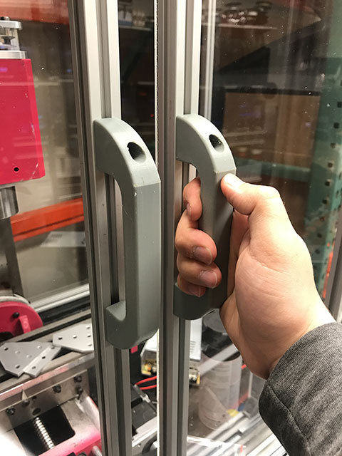
I also added sliding doors on drawer slides, and 3D printed some handles on our Zortrax M2 printers
Electronics and Control
Your choice of CNC controls seems to be almost religous. Some people swear by parallel ports and Mach3. Others say that LinuxCNC and and MESA cards are the way to go. There are standalone options, like the Centroid product line.
Given my familiarity with the firmware from past projects, I ended up going with what is arguably the weakest option – a Raspberry Pi controlling an Arduino running Grbl. I’m just doing 3 axis milling with basic probing, so this is a cost effective option. If I was doing this in any sort of professional context, I would probably not go with this solution. I’ve got the time and desire to tinker with this setup to make it work, but it’s definitely not been without its bumps.
I attempted to separate the high and low power components as best as I could. The spindle and stepper controllers live in a NEMA enclosure (That could stand to be a little bigger, admittedly…)
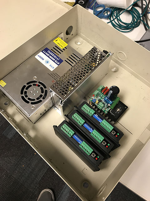
This enclosure sits at the front of the mill and has the main On/Off switch, as well as the Emergency Stop button.
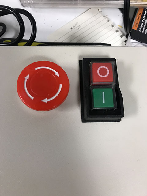
A quick aside about proper power switches for CNC devices. A serious CNC device should have a minimum of three power switches. The first, your main power interlock, is near the point where power enters the control box and should be fused. I have this power switch on the left side of the enclosure. Turning that switch on will power up the arduino and Raspberry Pi controller, but not any of the higher power components. A cable running from the main power interlock should go to a proper Emergency Stop button. The E Stop cable then goes to a Magnetic Power Switch. This type of switch is essentially a momentary switch attached to a latching relay, powered by itself. What this means is that if the power goes out temporarily, this switch will turn off then stay off. A normal toggle switch would allow power to flow again if there was a temporary outage. This isn’t behaviour we want in a machine that has the power to break itself!
Once all three of these switches are activated, the stepper motors and spindles are powered. Having a discrete E Stop switch lets you wire a signal cable into it, so your controller can know to pause when you’ve hit the E Stop (Remember, in our above setup hitting the E Stop powers down the Steppers and Spindle, not the controller!)
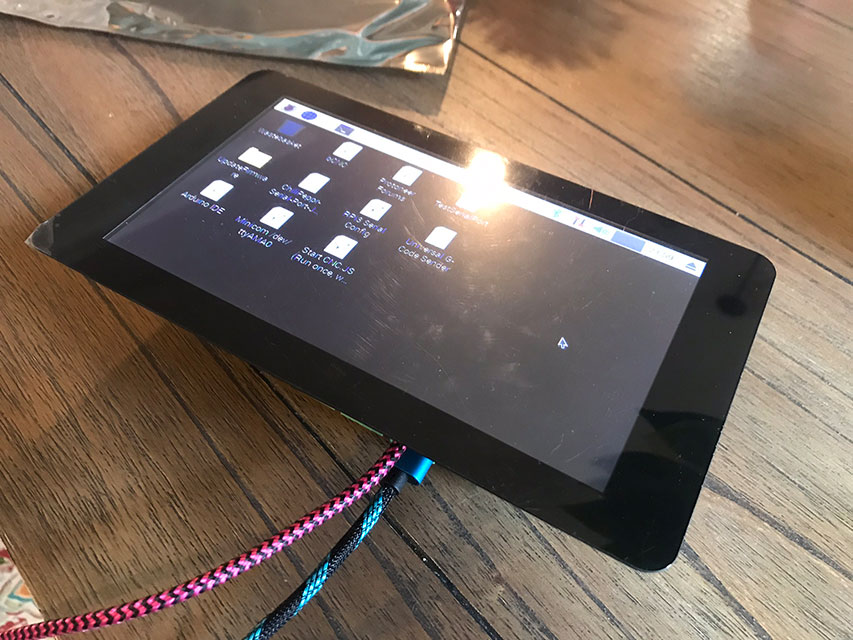
The controller is based around a Raspberry Pi 3 and the official 7” Pi Touchscreen.
I wanted to integrate a couple of push buttons for “Start” and “Stop” into this, so I found a nice aluminum enclosure from the local surplus bin
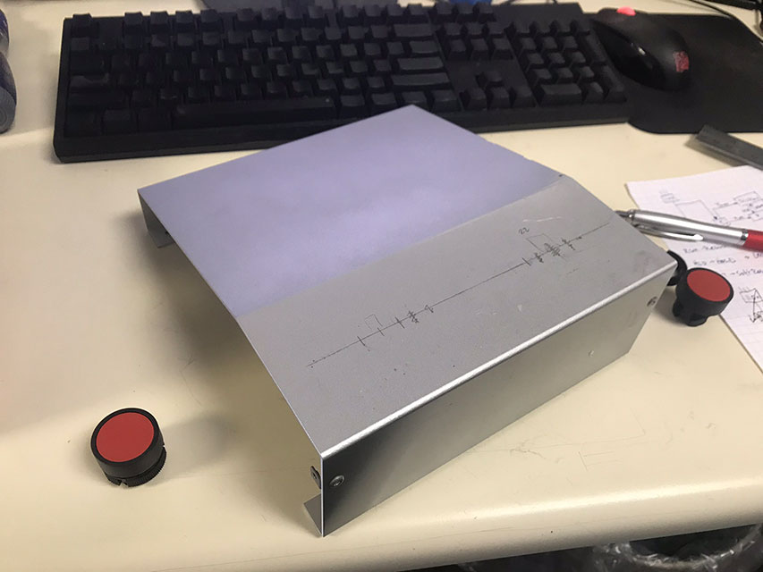
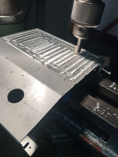
I drilled some holes for my buttons and laid out my cutout for the touch screen.
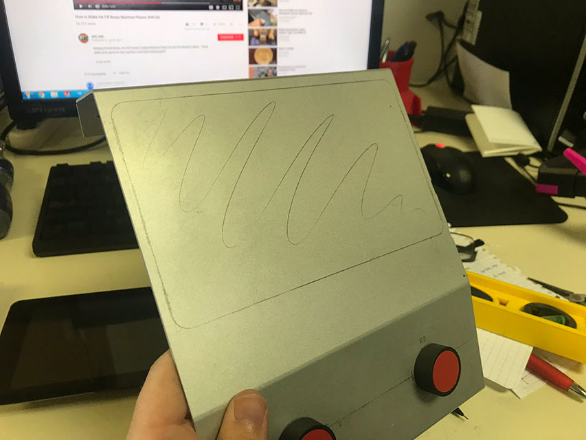
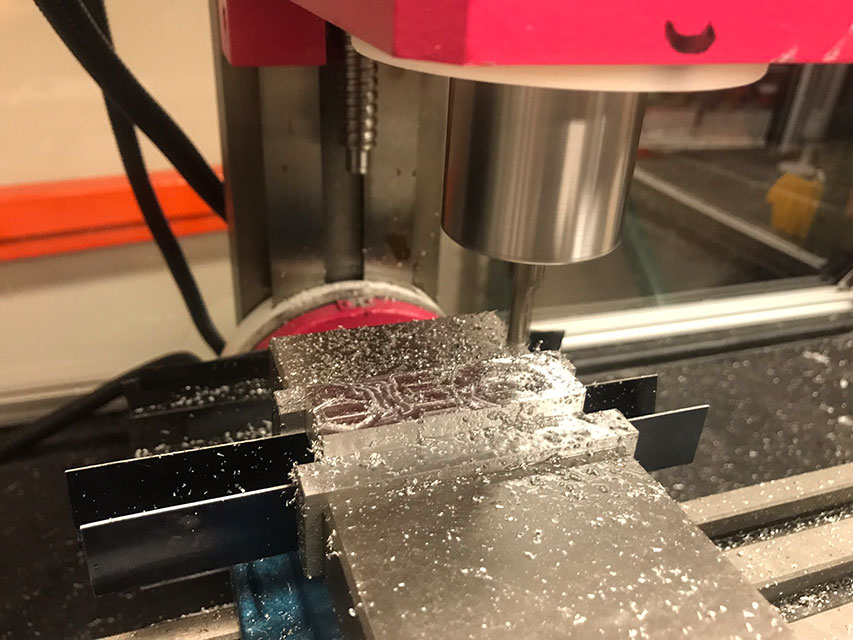
Using a very sketchy setup, I milled out the necessary pocket
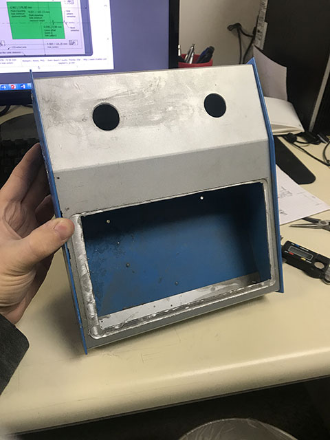
Everything seems to fit pretty well!
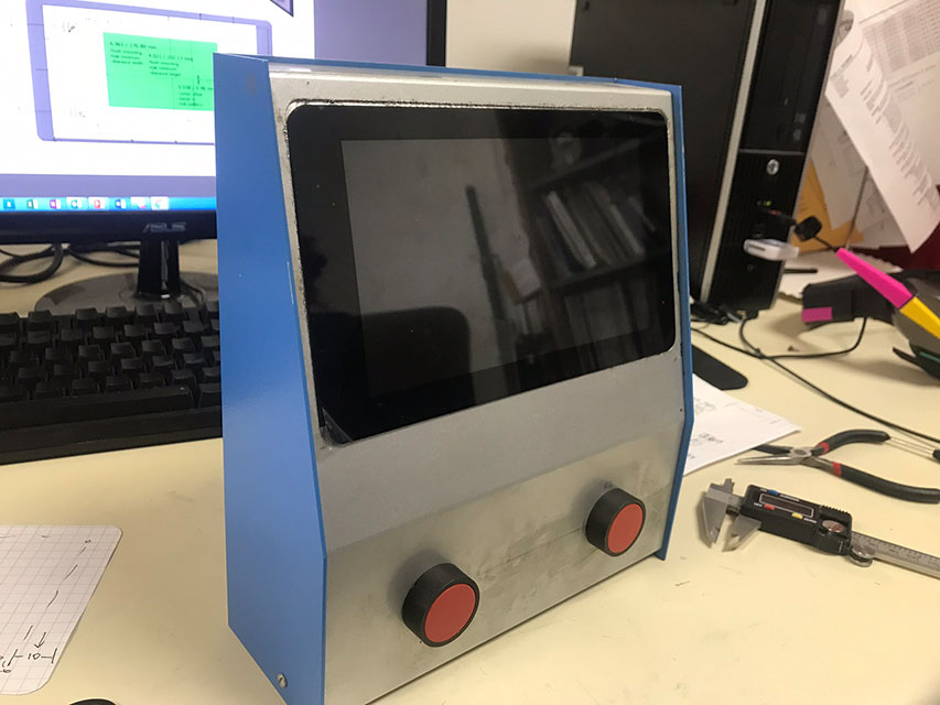
And a nice paint job brings it all together

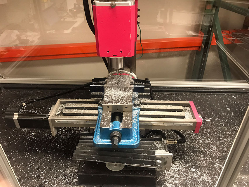
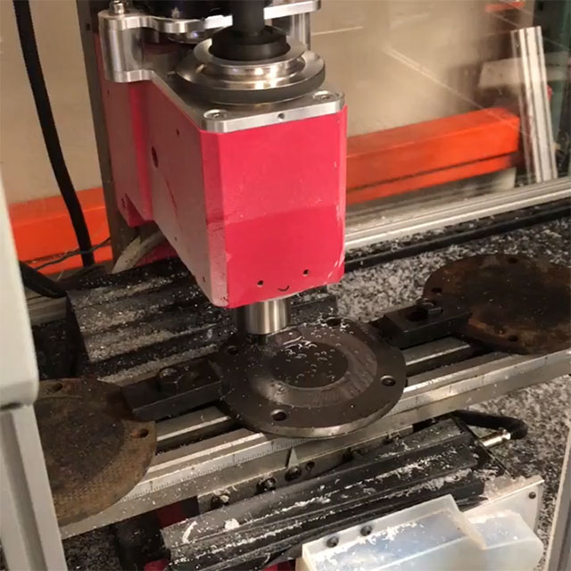
Time to see it move for the first time!
First Cuts
It’s been a journey to get to this point, but it’s all worth it for this moment… the first cuts!
And a wide shot. The mill is no longer this clean.
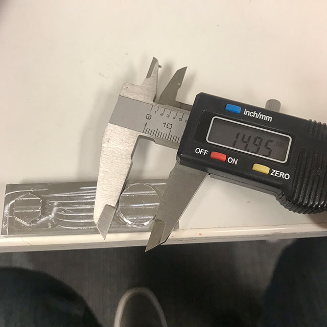
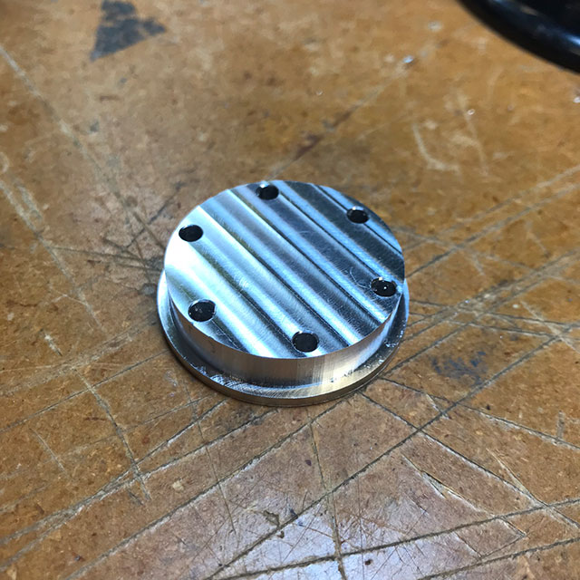
Here’s my test piece. It’s no Benchy, but there doesn’t seem to be a “standard” file for testing a CNC mill…
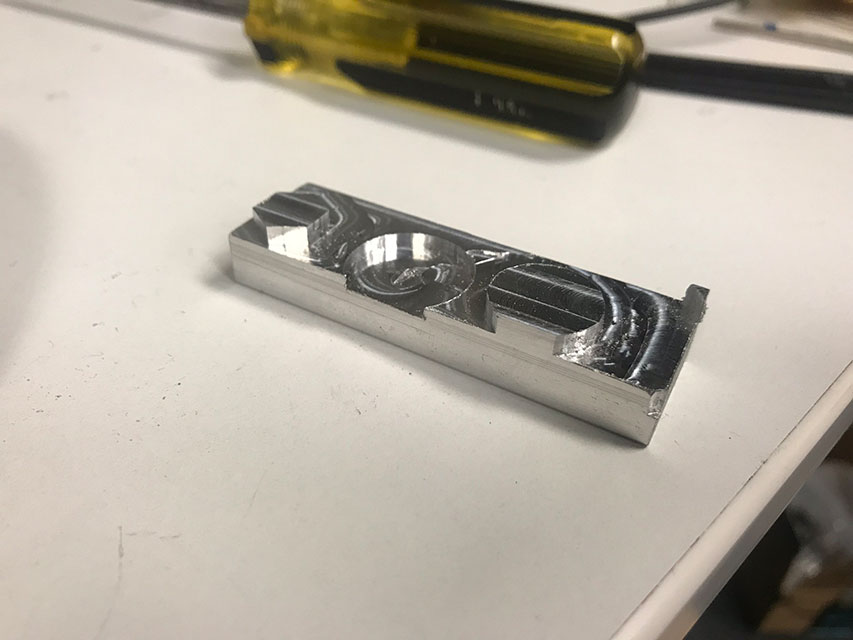
The dimensions are all pretty close. I’ve been getting used to tweaking and walking in critical surfaces (Like bearing pockets), but it’s still way easier to hit the proper numbers than with a 3D printer!
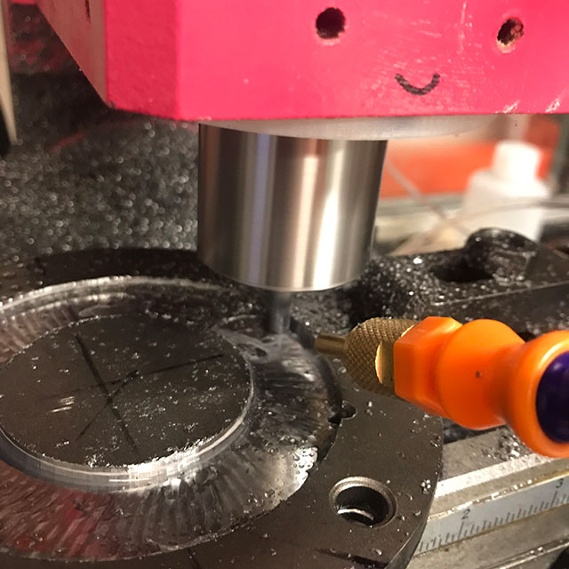
I’ve been working primarily in Aluminum, but my mill has also tested its mettle on some steel components:
I’ve also found the mill to be excellent at removing support material from some 3D printed parts. Obviously this has limitations, but for parts that just need a little off the top, it’s a quick and easy way to get consistent, fast results.
Future Improvements and Projects
To improve my workflow, I’ve added the Tormach Tooling System (TTS) to the mini mill. This makes it quick and easy to swap out tools.
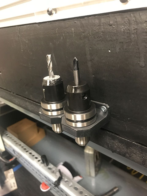
Unfortunately the control software I use, bCNC, does not have the ability to store tool offsets, which sort of eliminates one of the main advantages of the TTS. I ended up integrating a Tool Length Probe to deal with this annoyance. I’ll probably end up moving to a higher end control system eventually, but for now here’s a quick video showing the tool change probe in process:
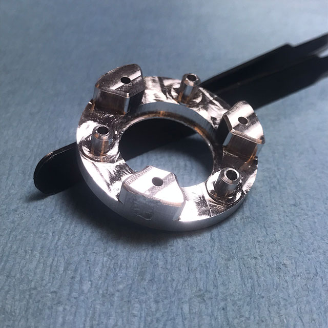
I’ve been using the mill to make parts that require tighter tolerances or stronger materials than a 3D printed part can afford, like mini planetary gear sets:

I’m sure we’ll see this mill make some appearances in future blog posts! Until then, the best place to see random updates and projects is when I post them to my Twitter account. That’s all for now!
Let me know what you think of this article on twitter @AchillePomeroy or leave a comment below!