Induction Soldering Iron
I need to solder large solid brass terminals onto the output of some vacuum relays. These terminals take a lot of energy to heat up, and I want as little of the heat transferred into the body of the relay as possible. Using a regular iron heats up the terminals too slowly, and too much heat creeps into the relay. We currently use a 100W iron, but there are still some issues with this approach. In order to get good thermal conductivity, we have to put a bit of solder on the outside of the terminal. It doesn’t affect the function of the terminals, but it is not aesthetically pleasing to have a blob of solder on a random side of the terminal.
We also need the terminals to be oriented a precise direction (flat side facing up!). Not changing the orientation of the terminals while soldering requires a very precise touch.
So my goal is to have a very localized, non-contact way of heating up a piece of metal. Sounds like a job for an induction heater!
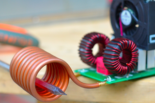
Induction heaters work by feeding a piece of metal through a series of coils with an AC current running through them. As the current in the in the coils changes directions, the magnetic flux changes as well. This changing flux induces an alternating eddy current into your piece of metal, which in turn will heat up.
I figured that using a induction heater for soldering would be pretty common, but if you google “Induction Soldering Iron”, you get a lot of results that look like regular soldering irons. For example:
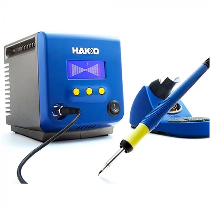
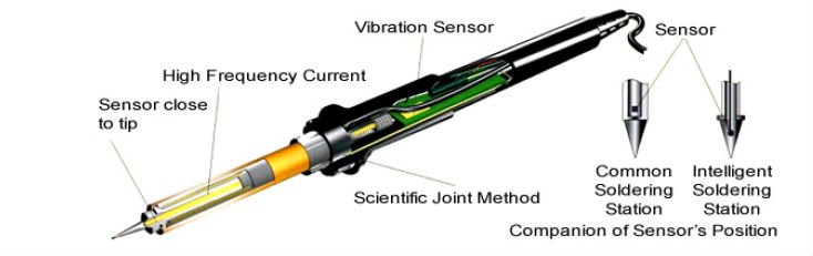
The tip of this iron has a a winding around it that lets the controller precisely control the tip temperature through induction heating.
Unfortunately, this won’t work for me. Time to build my own!
The Plan
Instead of using solder wire, use solder paste on the brass terminals. We can then use an off the shelf induction heater to heat the brass terminals to a temperature high enough to melt the paste and solder the connections.
We have to be careful to prevent overheating, though. The brass can easily get red hot and possibly even melt if the induction heater is left on for too long.
To address this, we’ll use a strategy found in the following video:
They use a relay module designed to pass 110V line voltage for a very precise amount of time.
We will use this to heat the brass terminals for exactly the right amount of time. And we might as well put it in a nicer box than they did!
Bill of Materials
The total cost of this build (as of writing this post in November, 2021) is $294.55. The control box portion of this build costs $58.56.
Obviously the majority of that cost is wrapped up in the induction heater. If you were to choose a more barebones version (Using, for example, a 120 watt heater instead of a 1 kW), you can get the cost down quite a bit. Since this tool will be used by others and is being built for work, I don’t mind paying extra for some extra power, safety features, and a nicely packaged product.
The Build
There are three main parts to this build.
The first is the enclosure cover, which needs slots cut in it to mount the relay module and the output outlet.
The second is the enclosure base, which needs a hole for the extension cable pass through, and the wiring inside.
The third is the proper setup for the induction heater, as a custom coil will be needed for the best performance in our application.
Enclosure Cover
I modeled the enclosure cover in Fusion 360, and loaded in a simple adaptive 3D recipe with a 6mm endmill.
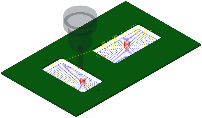
The 3mm radius was too big for the outlet and the relay, so I also cleaned it up with a 1.5mm endmill using REST machining 3D adaptive, and a 2D contour to finish the edges.
Enclosure Base
The enclosure base has a single 3/4” hole drilled in the side to accept the Cable Gland Strain relief. The end of the extension cord is cut off and fed through the strain relief, then stripped and connected to the the 9V power supply. The neutral and earth connections are connected to the terminals of the power outlet, and the live connection is connected to the input of the relay module. The output of the relay module is connected to the live terminal of the power outlet.
I’m not going to share photos of this section. If you can’t imagine what this wiring looks like, you probably should not be wiring 110v.
Now it was just a matter of setting up the relay and plugging something in!
Induction Coil
The coil itself is, surprisingly, the easiest and most straightforward part of this build. (Unless you purchase one of the cheaper modules and have to DIY it. of course!)
The only “modification” we made was winding our own coil using the provided wire. The pre-wound coils sent with the kit were all a bit too large. Larger coils still work, but to get the maximum performance you want the smallest coil possible.
I’m happy to report that this method of soldering works excellently!
Moving forward
I still need to spend some time finding the appropriate time spent soldering, but this has been a very satisfying little project to work on! I think it will improve our manufacturing process, and make our soldering easier, faster, and more consistent. Not a bad upgrade!
Let me know what you think of this article on twitter @AchillePomeroy or leave a comment below!